ROXIE/BEM-FEM Transfer Files
The HMO-file
The .hmo-file contains mesh information. It is produced by either the
HERMES 2-D parametric mesh generator or by the HyperMesh,
3-D mesh generator, using the edyson template file,
edyson_tech_doc.
The .hmo-file consists of six blocks: The first block contains component information (material names, coils), the second block contains load collector data, the third block vector collector information, the fourth block specifies all nodes, the fifth one the elements, and the last one additional boundary conditions. With ROXIE we only make use of blocks one, four and five which we will describe in detail in the following tables. The .hmo-file is organized as follows:
    `BEG_COMP_DATA`
    `...`
    `END_COMP_DATA`
    `BEG_NODL_DATA`
    `...`
    `END_NODL_DATA`
    `BEG_ELEM_DATA`
    `...`
    `END_ELEM_DATA`
The component data
The body of the component collector data block is structured as follows. One header record
| Variable | Type | Description |
|---|---|---|
NCOLL |
I8 | Total number of components |
A sequence of records with the component numbers and names
| Variable | Type | Description |
|---|---|---|
ICOLL |
I8 | Number of the component |
| n/a | String | Component name |
For numerical calculations the last component must have the name
SuperCoils. It represents the coils modelled by line-currents.
The nodal data
The body of the component data block is structured as follows. One header record
| Variable | Type | Description |
|---|---|---|
NNT |
I8 | Total number of nodes |
A sequence of records with the component numbers and names
| Variable | Type | Description |
|---|---|---|
IN_HMO |
I8 | Number of the node |
| XYZ(3) | 1X,F12.8 | Coordinates |
For BEMFEM-calculations the node numbers have to be in ascending order. For EDYSON they are only required to be unique. The coordinates are given in mm. Axisymmetric problems are discretized in the xy-plane.
Element data
The body of the element data block is structured as follows. One header record
| Type | Description |
|---|---|
| I8 | Total number of all elements in file |
| 1X,I8 | Total number of L2 elements |
| 1X,I8 | Total number of L3 elements |
| 1X,I8 | Total number of T3 elements |
| 1X,I8 | Total number of T6 elements |
| 1X,I8 | Total number of Q4 elements |
| 1X,I8 | Total number of Q8 elements |
| 1X,I8 | Total number of TH4 elements |
| 1X,I8 | Total number of TH10 elements |
| 1X,I8 | Total number of P6 elements |
| 1X,I8 | Total number of P15 elements |
| 1X,I8 | Total number of H8 elements |
| 1X,I8 | Total number of H20 elements |
A sequence of records which describe theelements
| Variable | Type | Description |
|---|---|---|
IEL_HMO |
I8 | Number of the element |
ICOLL |
1X,I4 | Element component number |
ICONF |
1X,I3 | Element config number |
KNE(1) |
1X,I8 | Number of the first node |
KNE(2) |
1X,I8 | Number of the second node |
| ... | ... | ... |
For BEMFEM-calculations the element numbers have to be in ascending
order. For EDYSON they are only required to be unique.
The element component number describes which material the element
belongs to. The material names are given in the component data block.
The element type number ICONF describes the element geometry as
follows:
ICONF |
Type | Description |
|---|---|---|
| 60 | L2 | Line element with two nodes |
| 63 | L3 | Line element with three nodes |
| 103 | T3 | Triangular element with three nodes |
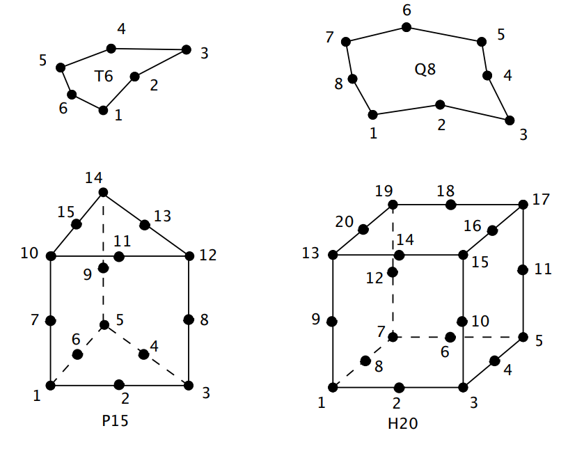
| 106 | T6 | Triangular element with six nodes |
| 104 | Q4 | Quadrilateral element with four nodes |
| 108 | Q8 | Quadrilateral element with eight nodes |
| 204 | TH4 | Tetrahedral element with four nodes |
| 210 | TH10 | Tetrahedral element with ten nodes |
| 206 | P6 | Pentahedral element with six nodes |
| 215 | P15 | Pentahedral element with fifteen nodes |
| 208 | H8 | Hexahedral element with eight nodes |
| 220 | H20 | Hexahedral element with twenty nodes |
With ROXIE we only use element types T6, Q8, P15 and H20. The element-wise node numbering of the respective types is depicted in Fig. 16.1.
The COR file
The .cor-file specifies the nodal coordinates for BEMFEM. It is basically a reference for the renumbering of the .hmo-file nodes. The first line is a header info line (version number, etc.). Then follows the header data line:
| Variable | Type | Description |
|---|---|---|
NNT |
I8 | Total number of nodes |
NDLN |
I7 | Number of degrees of freedom per node |
NDIM |
I6 | Dimension of the problem |
Then comes a sequence of records of the form:
| Variable | Type | Description |
|---|---|---|
IN |
Integer | Node number |
XYZ(3) |
Double | Nodal coordinates |
BSECT |
Integer | Boundary section (0:Interior FEM node, ><!-- -->0: BEM node on given boundary section) |
IDOF |
Integer | Number of degrees of freedom for current node |
The last line is the closing line:
| Variable | Type | Description |
|---|---|---|
FILEEND |
Integer | FILEEND=-1 denotes the end of the file |
The following table summarizes the different coordinate systems for the respective problem types:
| Geometry | (x_1,x_2,x_3) |
|---|---|
| Plain 2-D | (x,y,0) |
| Axisymmetric | (r,0,z) (z,r,0) |
| 3-D | (x,y,z) |
The ELE file
The .ele-file contains elemental data. It has one header line (version number, etc.) and one data header line:
| Variable | Type | Description |
|---|---|---|
IELEMS |
Integer | Total number of elements including boundary elements |
IMAXNOD |
Integer | Maximum number of nodes per element |
It follows a sequence of element records:
| Variable | Type | Description |
|---|---|---|
IEL |
Integer | Element number |
ITPE |
Integer | Element type number |
ICOLL |
Integer | Collector- (component-) number to which the element belongs |
INODS(21) |
Integer | A sequence of node numbers from .cor-file for the current element terminated by 0 |
A file closing line
| Variable | Type | Description |
|---|---|---|
FILEEND |
Integer | FILEEND = -1 denotes the end of the file |
The BDR file
The boundary condition data is given in the .bdr-file. One file header info line (with version number, etc.) is followed by a sequence of records of the form
| Variable | Type | Description |
|---|---|---|
INOD |
Integer | Node number (.cor-file) at which a boundary condition (BC) is specified |
IDOFTYP(10)) |
0X,I1 | Sequence of 10 flags each of which specifies a type of BC for each degree of freedom in the node; flag 0 means: no BC specified 1: homogeneous Dirichlet-condition 2: inhomogeneous Dirichlt-condition 4: pseudo-BEM-nodes for subsequent field calculation 5: inhomogeneity BEM-node 8: positive periodic condition 9: negative periodic condition |
VCOND(10) |
1X,12.5 | Sequence of BC vallues for each degree of freedom |
A file closing line
| Variable | Type | Description |
|---|---|---|
FILEEND |
Integer | FILEEND = -1 denotes the end of the file |
ROXIE uses only the BC flag 1 for homogeneous Dirichlet-conditions.
The SOL file
The .sol-file contains the computed results of BEMFEM. It has one file header info line and a sequence of time steps. For ROXIE there is only one time step available. Each time step is composed of a header line:
| Variable | Type | Description |
|---|---|---|
ITYP |
Integer | ITYP = -1 marks the header line of a time step |
IPAS |
Integer | Number of the present time step |
TIME |
Double | Absolute time of the present time step |
Then comes a sequence of subblocks containing problem dependent results; each subblock consists of a block header:
| Variable | Type | Description |
|---|---|---|
ITYP |
Integer | ITYP = -11 marks the block header line of the potential data block |
NCOL |
Integer | Maximum number of data columns (coordinates and/or reults) |
NROW |
Integer | Number of rows for the present block (0=not available) |
The header is followed by a sequence of records:
| Variable | Type | Description |
|---|---|---|
IN |
Integer | Node number |
XYZ(3) |
Double | Nodal Coordinates |
V(NCOL-3) |
Double | Results (vector and/or scalar potential) |
The block is closed by a line
| Variable | Type | Description |
|---|---|---|
BLOCKEND |
Integer | BLOCKEND = -99 marks the block closing line. |
And the time step is closed by
| Variable | Type | Description |
|---|---|---|
TIMESTEPEND |
Integer | TIMESTEPEND = -9 marks the end of the current time step. |
The SRC file
BEM-FEM coupled problems can be driven by a source potential (φ_mathrm{S}, mathbf{A}_mathrm{S}) due to impressed charges or currents in the BEM domain. This potential should be given at the locations of the boundary nodes in the following structure. The first line yields
| Variable | Type | Description |
|---|---|---|
BNODES |
I5 | Number of nodes belonging to the boundary |
Then follows a sequence of records with node numbers, nodal coordinates and prescribed potential values.
| Variable | Type | Description |
|---|---|---|
| IN | I5 | .cor-file node number |
| XYZ(3) | 1X,E18.11 | Coordinates |
| POT(3) | 1X,E18.11 | prescribed source potential, see below |
The node numbers must be in ascending orders and the number of records
must be equal BNODES. The degrees of freedom of the impressed source
potential depend on the problem type as follows:
| Problem Type | DOF1 | DOF2 | DOF3 |
|---|---|---|---|
| 2-D | A_z | ||
| 2-D Axi-symm. | rA_φ | ||
| 3-D vector Pot. | A_x | A_y | A_z |
| 3-D scalar Pot. | φ |
The EVAL.LOC file
The BEM-FEM coupling allows the evaluation of the reduced potentials and fields at arbitrary points in the BEM domain once the problem has been solved. Such additional evaluation points are given in the eval.loc-file with the following structure. The header record yields
| Variable | Type | Description |
|---|---|---|
NKSI |
I5 | Number of additional evaluation points |
HFD |
1X,E12.5 | Parameter h for finite differences |
The header is followed by a sequence of records with the coordinates of the evaluation points:
| Variable | Type | Description |
|---|---|---|
I |
I5 | Number of evaluation point |
V(3) |
1X,E18.11 | Coordinates |
The EVALBFOUT.LOC file
On exit of a BEMFEM run an output file is written that yields the potential in the additional evaluation points specified in the eval.loc-file. The header record reads:
| Variable | Type | Description |
|---|---|---|
NKSI |
I5 | Number of additional evaluation points |
Then follows a sequence of records with the results:
| Variable | Type | Description |
|---|---|---|
I |
I6 | Number of the evaluation point |
V(9) |
1X,E18.11 | Coordinates and result DOF, see below |
The degrees of freedom that appear depend on the problem type:
| Problem type | DOF1 | 2 | 3 | 4 | 5 | 6 | 7 | 8 | 9 |
|---|---|---|---|---|---|---|---|---|---|
| Magnetic mathbf{A} 2-D Axi 3-D |
x | y | A_z | B_x | B_y | & | & | ||
| Axi | z | r | rA_φ | B_z | B_r | & | & | ||
| 3-D | x | y | z | A_x | A_y | A_z | B_x | B_y | |
| Magnetic φ 3-D |
x | y | z | φ | B_x | B_y | B_z | & |
The mathbf{B} field is computed from the potentials by means of
finite differences with the parameter HFD.
The PLOTBF.OUT file
Some results from a computation for postprocessing are written to a textfile. In 2-D, this is the plotbf.out-file. It starts with a header record
| Variable | Type | Description |
|---|---|---|
NELT |
Integer | Number of finite elements |
Then come the finite-element headers, each one followed by a sequence of nodal records. The element header has
| Variable | Type | Description |
|---|---|---|
IEL |
I5 | Number of the element as specified in the .ele-file |
INEL |
I5 | Number of nodes in the element |
IGPE |
I5 | Properties group number as specified in the .ele-file |
MUR |
1X,E12.5 | Average relative permeability of the element |
The nodal records of each element read
| Variable | Type | Description |
|---|---|---|
KNOD |
I5 | Internal number of the considered node (not related to .cor-file) |
XY(2) |
1X,E12.5 | x-, y-coordinate |
BXY(2) |
1X,E12.5 | B_x-, B_y-component |
AZ |
1X,E12.5 | A_z-component |
The results are total fields (sum of reduced- and source fields). For Q8
quadrilateral elements a 9th line is added with empty KNOD entry. This
record contains the field and potential values in the center of the
element.
The PLOTBF3-D.OUT file
The postprocessing file for 3-D calculations is somewhat differently structured than the plotbf.out-file. There is one header record
| Variable | Type | Description |
|---|---|---|
RELT |
Integer | Number of boundary elements |
A sequence of records for each boundary element, each one followed by a sequence of nodal records.
| Variable | Type | Description |
|---|---|---|
IEL |
I5 | Consecutive number of the boundary element |
INEL |
I5 | Number of nodes in the element |
The nodal records read
| Variable | Type | Description |
|---|---|---|
KNOD |
I5 | Internal number of the considered node (not related to .cor-file) |
XYZ(3) |
1X,E12.5 | x-, y-, z-coordinate |
A(3) |
1X,E12.5 | A_x-, A_y-, A_z-component |
B(3) |
1X,E12.5 | B_x-, B_y-, B_z-component |
Additional files
The following files are not further detailed in this manual:
| File | Description |
|---|---|
.DAPA |
Magnetization curves for BEMFEM |
.dyn |
Contains integral and mechanical result quantities for each time step |
.ght |
Binary file which contains the BEM matrices of a previous run |
.inp |
BEMFEM input file |
.out |
Collects messages from a BEMFEM run |