The Xroxie User's Interface
The Graphical User Interface
Overview of the Tcl/Tk widgets
The structure of the Chapters 2-10 is imposed by the input widgets of the Tcl/Tk-based graphical user interface Xroxie. Xroxie is an X-windows program designed to supplement users of the ROXIE program with a graphical user interface (GUI). The program is intended to work with ROXIE version 5.2 and higher and aims to fulfill the following criteria: 1) To present the users of ROXIE with a single consistent interface through the complete process of creating new coil calculations. This includes creating the ROXIE input file, editing the material file, running the roxie program and viewing the results of the ROXIE calculation. 2) To assist in the editing of input files by providing the user with descriptions, hints and/or help boxes for the data required in constructing the input file.
When file is created or loaded into Xroxie, the data is presented as a form in the main Xroxie window. The layout of this form in general follows the policy of the ROXIE input data file of splitting the data into discrete sections, however the following points should be noted.
-
Any sections of the form that are irrelevant for the options specified are not displayed on the form and cannot be edited by the user. For instance, the plot 3-D information is unavailable until both the LEND and LPLOT options are switched on. However, any data stored in such sections is retained until a new form is edited or Xroxie is closed down, and can be reinstated by selecting the appropriate options.
-
The ROXIE data file contains a considerable amount of information, too much to display all at once in a windowing environment. As a solution to this problem a method has been devised where each section of the form can either be viewed or 'rolled up' using the push button at the left hand side of the section label. This enables space to be saved by temporarily hiding sections not being edited. In addition, the whole form can be scrolled up or down using the scroll bar at the side of the window.
The philosophy behind the form is that anywhere a blank entries exists on the form, Xroxie, and ROXIE, expect data to be supplied. However some tables allow blank entries (such as the plot 2-D 'field'). Xroxie will check for missing information in a form before it is saved or ROXIE is run. However, due to the complex interaction of the data in the input file, Xroxie cannot check the validity of this data.
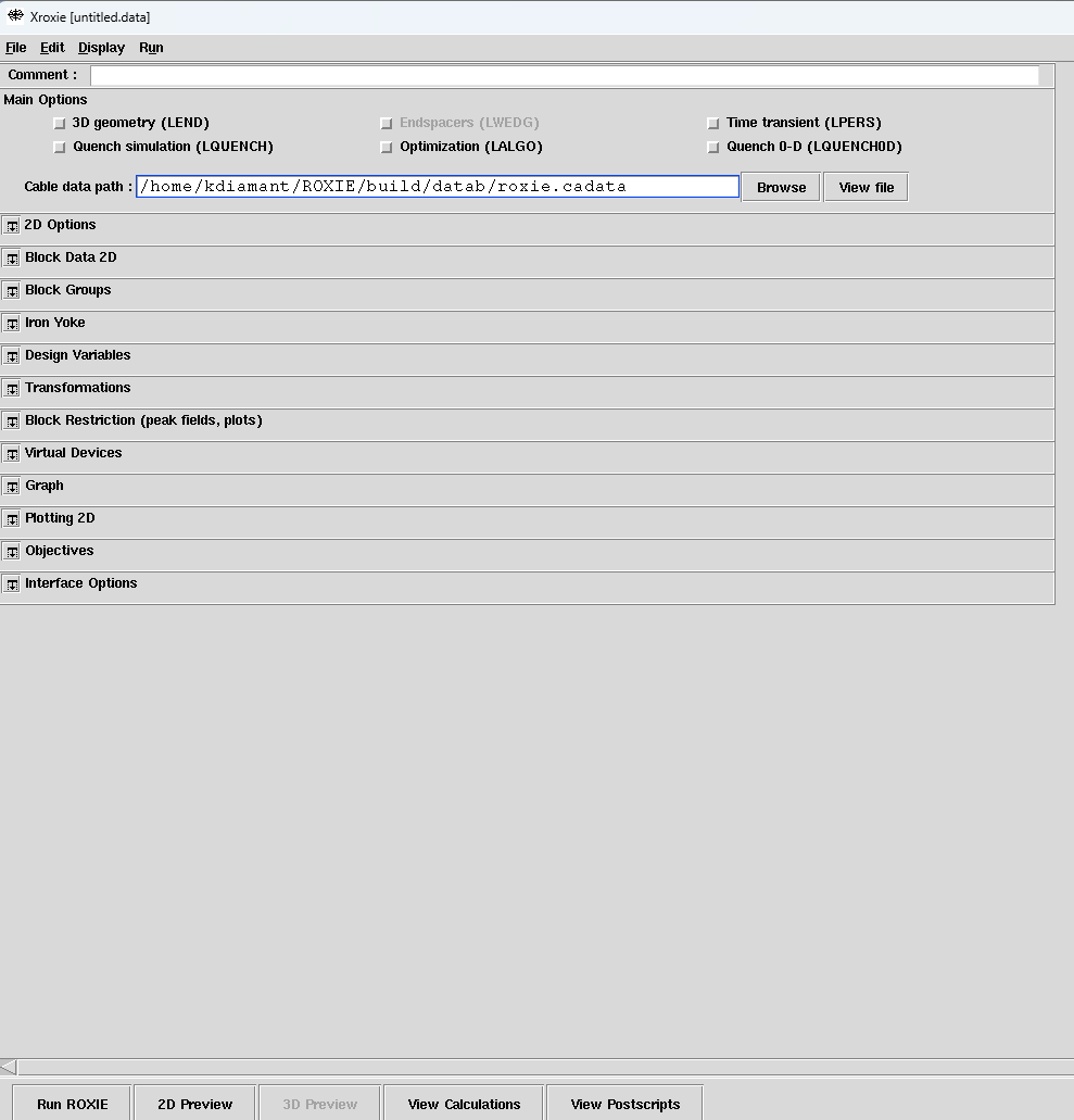 View of the Xroxie Graphical User Interface. All widgets are closed
Comment:
Give a description (of up to 62 characters) for your model in the "Comment:"-line.

The "Comment:"-line will be plotted on top of every postscript plot.
Main Options
This section holds the options which affect the overall operation of ROXIE. Many of them affect what data is required from the rest of the form. See the ROXIE documentation for specific information on each option.

2D Options
The 2D Options-widget yields functionalities that are generally more closely related to 2-D analytical field calculations. Most of them will be explained in greater detail below.

3-D Global Information
This section holds the information and options required to configure ROXIE for 3-D coil end calculations. Certain options, if turned on, require additional information to be specified elsewhere on the form. This section is only available if the option 'LEND' is turned on.
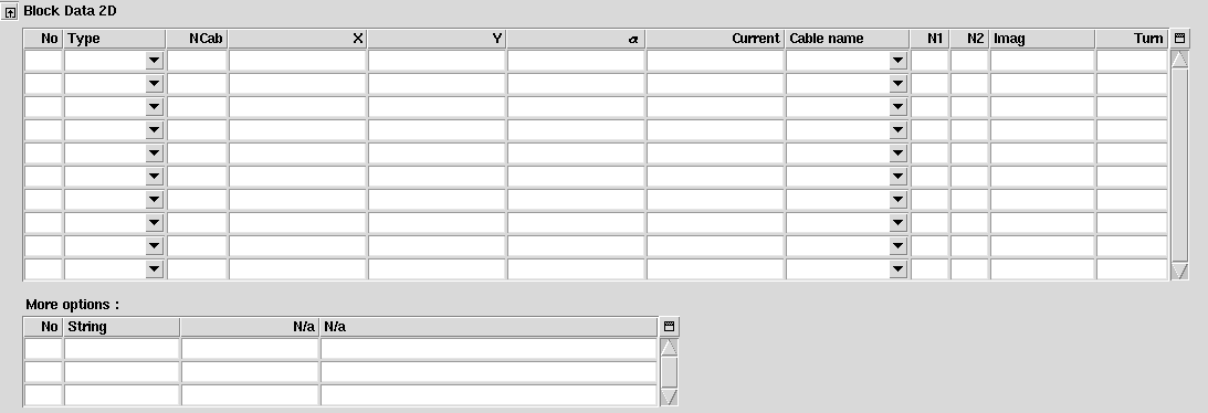
Block Data 2-D
Here the input data for the coil cross-section has to be specified. There are different type of coils in the dropdown menu of "Type". Clicking on the widgets of every column (Type, NCab, etc..) will give some help boxes in order to fill out the tables accordingcly. Note that the column names are adjusted for different types in order to help the user specify the correct geometry. For instance, for rectangular coils we need X and Y values, like below. If we select cosine theta magnets, values for R (radius of the winding mandrel) and φ (inclination angle) need to be specified and the repsective column names appear.
Under "More options" other 2D related options can be specified. Right clicking in "String" column produces the available extra options.
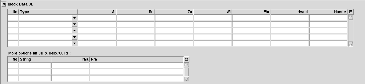
Block Data 3-D
As "Block Data 2-D" but for the input data of the 3-D coil ends. Only available if the "3-D Coil Geometry"-option in the "Main Options" is 'on'.
In "More Options" we can specify geometries for Helixes and CCTs, but also we can curve the designed geometries.
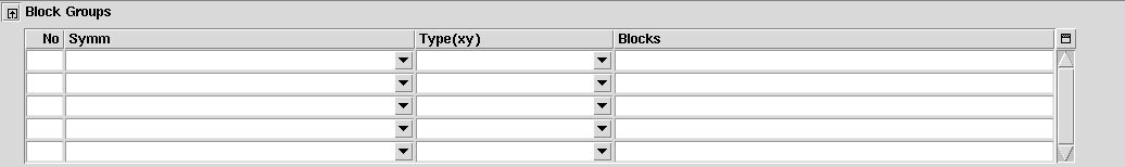
Block groups
This table is used to define block groups or layers of coil blocks for more convenient cross-section modeling.
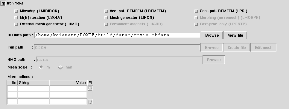
Iron Yoke
This widget is responsible for the Iron Yoke addition, meshing and coupling of BEM-FEM methods.The user can either select an iron file path or edit/create it via Xhermes, by clicking on "Edit mesh" button. Further documents for Xhermes capabilities and iron examples can be found in Roxie Website. Xhermes has a user-friendly GUI and is intuitive. The user can create the geometry and mesh there and later trigger the corresponding Roxie Settings from the picture below. B-H curve can be selected from roxie database.
Design Variables
This table stores the lower and upper bounds of the design variables of an optimization run. The 'String' field in the table can take a single pre-defined symbol. This may be selected from a menu by right-clicking in the appropriate cell. The table menu holds an option to read in scan data produced by a previous run of the ROXIE program. This data is used to define starting values in the 'Xs' column. The table is also used for static geometrical transformations. Some methods and functionalities use the "Design Variables"-table to read in model parameters or other data.
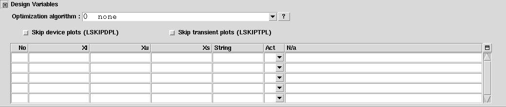
During an optimization run, the design parameter is varied between Xl and Xu, starting with Xs. If we want to abuse design values for transformations, i.e., if we want that they are always applied but not varied during optimization, we set Xl=Xu=Xs. It is important to note that the design variables are read at every ROXIE run and the Xs values are always applied - even if no optimization has been chosen.
- In the "Act"-field, if we do not select "All blocks", we may need to specify the Blocks, Conductors, Strands, etc. In the given cell we enter space-seperated
integer numbers. The "
n-m"-entry is stored as "n (n+1) (n+2) ... (m-1) m". For example,10-1218-2022is stored as10 11 12 18 19 20 22. Note that per line no more than 20 layers, blocks, conductors or strands are stored!
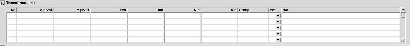
Transformations
This table is responsible for 2D or 3D transformations that can act on blocks, groups condutors. Different geometry manipulation is offered like tilting, shifting or rolling around different axes.
Block Restriction
This data line contains the numbers of those blocks in which field calculations on the strand-level are to be performed. This is important specifically for 3D calculations in ordert to save computation time.

Virual Devices
In Virtual Devices the user can define field quality calculations in a circle reference like harmonic coils, in points given in a matrix or along a given and defined path. Also K-value sensitivity factors can be calculated.
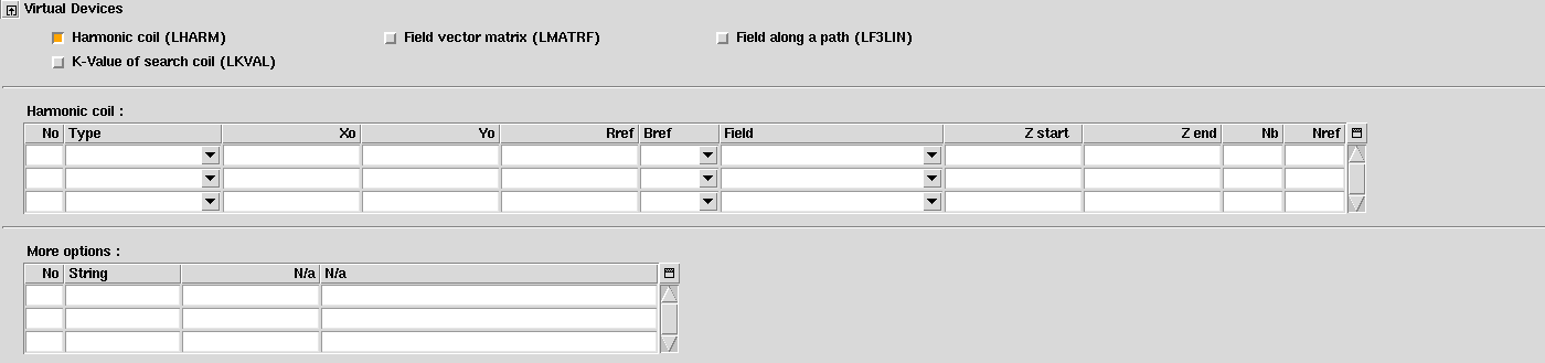
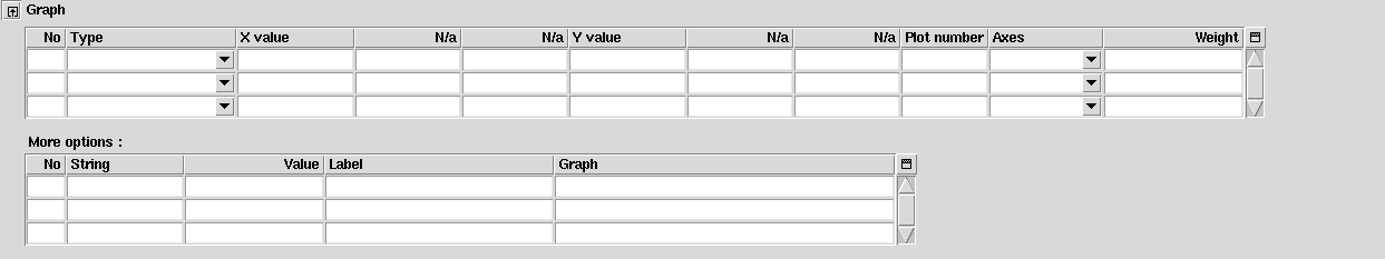
Graph
Here settings related graphs and plots can be defined. The user can give labels and titles to the graphs, combine plots and further more. This is especially useful for extracting and presenting results.
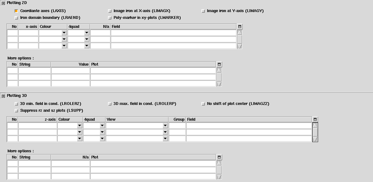
Plotting Information 2-D and 3D
The postscript plots produced during a ROXIE run are defined here (2-axis graphs are defined in the "Objectives"-widget). Only available if the "Postscript Plots"-option in the "Main Options" is 'on'. As "Plotting Information 2-D" for 3-D plots. Only available if the "Postscript Plots"- and "3-D Coil Geometry"-options in the "Main Options" are 'on'.
Objectives
Here we define an objective function for an optimization. The table is also used to observe design variables during an optimization run or to store plot data during transient calculations. The 'String' and 'Oper' fields in the table can take a single pre-defined symbol. This may be selected from a menu by right-clicking in the appropriate cell.
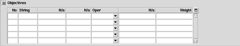
With the PLOT-operand in the "Objectives"-table each objective can be plotted into a graph during optimization runs and during time-transient and transfer-function calculations.
The columns of the "Objectives"-table are described below.
| Variable | Description |
|---|---|
| Ne | Row number. |
| String | Right-click in a field gives a list of objectives for optimization or plotting. |
| Oper | Operand in the objective function or PLOT-operand. |
| Weight | The weighting factor for the objective. Also used with the PLOT-operand. |
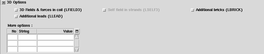
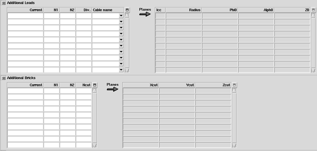
Additional Leads & Bricks
For Additional leads or bricks we need to activate the 3D Geometry from "Main Options" and in the "3D Options" Widget that appears "Additional leads" and/or "Additional bricks" needs to be toggled on.
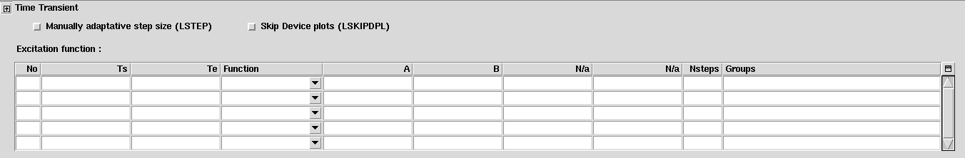
Time-Transient Effects
This widget holds information on the calculation of time-transient effects in superconductive material (persistent currents, ...). Only available if the "Time Transients"-option in the "Main Options" is 'on'.
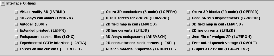
Interface Options
The user can choose between different output files that act as interfaces to other programs. Also some post-processing options are hidden in this widget.
2D Preview Window
It is possible to preview the geometry of the coil being editted in the form by selecting the menu option 'Run | Open preview window'. If there are no errors in the definition of the input file then a new window will be opened displaying a cross-sectional image of the coil as in the following screen grab.
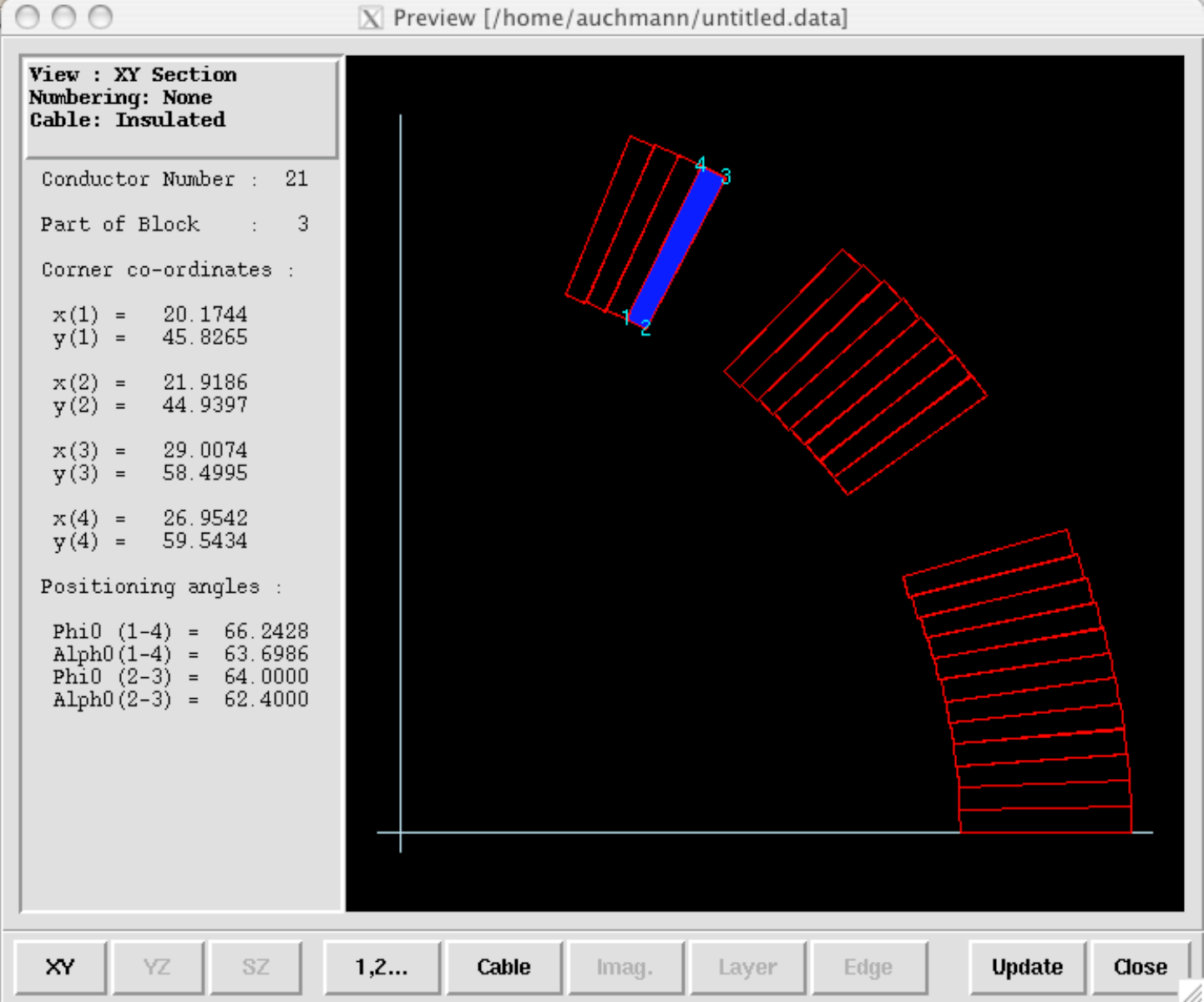 The coil-geometry preview window.
This display is controlled by the following buttons to be found at the bottom of the window:
-
XY will display the coil's 2-D cross-sectional view in the X-Y plane.
-
YZ will display the coil end's cross-sectional view in the Y-Z plane. This button will be unavailable if no coil end is defined (LEND is switched off).
-
SZ will display the coil end's developed view in the S-Z plane. This button will be unavailable if no coil end is defined (LEND is switched off). The cable type will automatically revery to being 'bare' when this view is chosen.
-
1,2... will cycle between showing no numbering, showing block numbering, and showing cable numbering on the image.
-
Cable will toggle between displaying the cable bare or insulated.
-
Imag. will cycle between showing all blocks, non-imaged blocks, and imaghed blocks in the YZ view. For use when two sets of image blocks are being connected at the coil ends and not available if no imaged blocks are specified.
-
Layer will cycle through the different layers of the coil on the SZ view. For each layer the outer (34) edges will be shown in the top half of the image and the lower (12) edges will be shown in the bottom half.
-
Edge will toggle between showing the inner (12) and outer (34) edges of the coil in the SZ view. Only of use if one layer is defined and is used when two sets of image blocks are being connected at the coil ends.
-
Update will update the images according to the current state of the Xroxie form. This button will need to be used if the Xroxie form is modified or a new form is loaded.
-
Close will close the preview window.
In the XY and YZ sectional views geometric information for a conductor can be obtained by moving the mouse cursor over it. The conductor will be highlighted and various geometric information will be displayed in the box to the left of the image, depending on whether the conductor is displayed as a bare or insulated cable. In addition, by dragging a rectangle over the image using the mouse it is possible to zoom in on a particular area of the coil. To re-instate the full view click on the XY,YZ or SZ as appropriate. It should be noted that the ROXIE program is called to perform the calculations required to create these images and this has several implications:
-
The paths to the ROXIE executable and data file should be correctly set under the menu option 'Run | Set paths'.
-
All relevant data required in the form to create a correct input data file must be present, even if not required to produce the geometry calculations. For instance, there should be no blank cells on the form. If ROXIE detects any errors with the form when trying to run then these errors will be reported directly to the user via a dialog window.
-
If a non-zero contraction factor is specified in the "Global Information" widget, the numerical x- and y-values in the preview window will be adjusted by the factor.
3D Preview Window
The virtual reality viewer view3dscene is delivered with ROXIE.
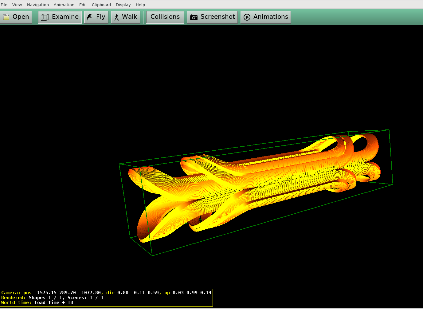 The 3D preview window
Menu descriptions
File menu
-
Clear form clears all data from the form, resets all options except those which are intended to be true by default, and re-titles the form as 'untitled.data'. If the existing form has been changed and not saved then the user will given the option to save the form before continuing.
-
Open form ... displays a dialog box requesting a new data file from the user to be loaded into Xroxie. If the existing form has been changed and not saved then the user will given the option to save the form before continuing. Upon loading the new form Xroxie will perform a series of checks for invalid data. If a discrepancy is found then a dialog box will pop up describing the problem(s). The user can then choose to ignore the problem and if necessary correct the file in Xroxie, or start up a text editor and fix the file 'by hand'. This will be necessary when data is missing from the file.
-
Reload form ... reloads the form to be loaded into Xroxie. Like above, if the existing form has been changed and not saved then the user will given the option to save the form before continuing. This is useful for experimenting with the design and mostly for 2D or 3D preview.
-
Save form saves the current form in place of its existing file under the same name. If data is found to be invalid or missing from the form a warning is given and the save aborted. Any old version of the file is saved under the existing filename followed by a tilde(\~) character.
-
Save form as... displays a dialog box requesting a new filename under which to save the current form, retitles the form and saves it under the new name. If a file exists with the given name a warning is given before it is overwritten. If data is found to be invalid or missing from the form a warning is given and the save aborted.
-
Exit closes down Xroxie. If the existing form has been changed and not saved then the user will given the option to save the form before continuing.
Display menu
-
View form as text will withdraw the Xroxie window and display the form within the text editor specified under 'Run|Set paths...'. This facility has been provided so that existing users of ROXIE, who are used to the textual input format, may view the form using the native ROXIE format. NOTE: It has not been intended for the file to be editted using the viewer. As Xroxie and the viewer work on separate copies of the file, any editting done in the viewer will have to be saved and then re-loaded into Xroxie for the changes to be seen.
-
Maximize all sections will expand all the roll-up sections of the form that are currently minimized, thus displaying the complete details of the form.
-
Minimize all sections will roll up all the sections of the form that are currently maximized, thus displaying only the headers for each section.
-
Autofit all tables will resize ALL the tables in the form, whether displayed or not, to the exact amount of rows required for the data in each table.
Run menu
-
Run ROXIE. Runs the ROXIE program.
-
Open cable data window. Editting the 'roxie.madata' file.
-
Open preview window. Previewing the coil geometry.
-
View calculations. Views the calculations file from the last ROXIE run associated with the input file being editted.
-
View postscripts. Views the postscripts file from the last ROXIE run associated with the input file being editted.
-
Print calculations. Prints the calculations file from the last ROXIE run associated with the input file being editted.
-
Print postscripts. Prints the postscripts file from the last ROXIE run associated with the input file being editted.
-
Set paths... is used to set paths to various programs and files that Xroxie needs to function correctly. When run for the first time Xroxie will create a file in the users home directory called .xroxiepath. This file retains the paths set by the user. To re-inisiate the default settings for Xroxie this file can be deleted.
How to use the tables
Various sections of the Xroxie form use tables, similar to the one pictured above, for the entry of arrays of data. The following points should be observed when using these tables:
-
The tables have no maximum length and grow as entries are added. As different installations of ROXIE set varying limits on the size of arrays that can be entered, Xroxie does not check to see if these limits have been exceeded.
-
When entering data into the table do not leave blank lines between lines of data. Xroxie looks for the last row containing entries to decide how many rows are specified when creating a ROXIE input file, and will interpret intermediate blank lines as missing data.
Navigating and editting tables
Below is a list of the most important editing facilities offered by the Xroxie tables. Where the mouse action refers to the 'Menu', the button at the top right of the relevant table should be clicked. This will reveal a menu from which the appropriate choice can be made.
| Input method | Keyboard | Mouse | Input form | Cable |
|---|---|---|---|---|
| To perform action | ||||
| Move to previous cell | <Shift-Enter> | X | X | |
| Move to next cell | <Enter> | X | X | |
| Move to cell above | <Up Arrow> | X | X | |
| Move to cell below | <Down Arrow> | X | X | |
| Insert blank line into table | <Ctrl-O> | X | X | |
| Cut row into table's clipboard | <Ctrl-W> | X | X | |
| Copy row into table's clipboard | <Ctrl-C> | X | X | |
| Insert table's clipboard before row | <Ctrl-Y> | X | X | |
| Duplicate multiple lines | <Ctrl-D> | Menu | ||
| Delete multiple lines | Menu | |||
| Show more rows on table * | <Ctrl-Down> | Menu | ||
| Show fewer rows on table * | <Ctrl-Up> | Menu | ||
| Find and replace | <Ctrl-F> | Menu | X | X |
| Renumber first column | <Ctrl-R> | Menu | X | |
| Sort ** | <Ctrl-S> | Menu | X | X |
| Help on column | <Shift-F1> | Click in header | X | X |
| Move to beginning of entry | <Ctrl-Home> | X | X | |
| Move to end of entry | <Ctrl-End> | X | X | |
| Delete entry | <Ctrl-/>,\<Delete> | X | X | |
| Show geometry columns *** | <Ctrl-F1> | Menu | ||
| Show property columns *** | <Ctrl-F2> | Menu | ||
| Show description *** | <Ctrl-F3> | Menu |
* When using the 'Duplicate multiple lines' option the line numbers to be entered should be the logical row numbers of the table, these are NOT necessarily the same as the numbers listed in column one of the table. Choosing the renumber option will ensure that the numbering in this column and the table row numbering are the same.
** To show more or less rows for the cable table the window containing the table should be resized.
*** Sorting for tables in the input form is automatically performed on the first column of the table. However, for the cable form sorting may be done on any field. If the <Ctrl-S> keyboard accelerator is used sorting will be done on the column that holds the input focus.
**** When paging the table for the conductor information using Ctrl-F1, F2 & F3 the keyboard focus must be in the 'Material' column.
Running the ROXIE program
Once the form has been completed, the ROXIE program can be run without leaving the Xroxie enviroment. To do this select the menu option 'Run | Run ROXIE'. Providing all the settings in the 'Run|Set Paths...' menu option are correct and the ROXIE support files are available the ROXIE program should run over the file seamlessly in a new Xroxie window. A display of execution time is shown at the bottom of the window.
To abort a run prematurely press the Abort button. This will cause an
interuption in the ROXIE RUN. (/em Note: This should take effect
immediatly but at present there is a bug which causes Xroxie to wait
until the next output from ROXIE before aborting).
Once ROXIE has finished the Abort button will change to CLose and
there will be a message at the bottom of the screen. If this reports an
error then there was a problem:
-
A) With the set up of Xroxie or the settings in the 'Run|Set paths...' m,enu option.
-
B) A problem with the input file, in which case the ROXIE output will show a dragon symbol.
-
C) An abnormal abortion of the ROXIE command or the runroxie script.