Coil Modeling
The ROXIE program includes routines for defining the geometry of coil cross-sections made of Rutherford type superconducting cables or rectangular shaped braids. The geometric position of coil-block arrangements in the cross-section of the magnets is calculated from the following input data:
-
In case of cos nΘ magnets, the number of blocks, the number of conductors per block, conductor type (specified in a cable data base), radius of the winding mandrel, as well as positioning and inclination angle of the blocks. The grading of the current density is taken into account by a discretization of the cable into N1 * N2 strands, where N1 is the number of strands in the narrow direction, and N2 is the number of strands in the direction of the broad side (2*18 in case of the LHC outer layer dipole cable).
-
In case of window frame magnets, the number of blocks, the number of conductors per block, conductor type, x and y position of the lower left corner of the block, and inclination angle with respect to the x-axis.
-
In case of beam pipe magnets, the number of blocks, the number of conductors per block, the radius of the winding mandrel, the positioning angle of the first conductor and the increment angle for the subsequent conductors.
-
In case of hollow conductors (cable in conduit), the geometry is created as in the cases above. From the cable boundary an inlaying cylindrical conductor with N1 arc segments is generated. The arc segments have an inner radius such that exactly one strand is inscribed within each segment. In the ROXIE input file the parameter N2 has to be set to zero.
2-D coil modeling
Main options
| Option | Description |
|---|---|
| Symmetric Coil | Make use of a symmetry in the coil geometry modeling. |
| Layer Definition | Define layers of coil blocks, possibly each with a different symmetry. |
| Wedge/Endspacer | Compute the shape of wedges and of the end-spacer in the xy-plane for the plot option WEDGE. The wedges are only calculated correctly with the "Symmetric Coil"-option. |
The symmetry- and layer options are described in Section Cosine Theta Cross Section.
Global information
| Option | Description |
|---|---|
| Cond. Alignment OD | 'off': align the inner side of the conductors on the winding mandrel; 'on': align the outer side of the conductors on a radius r_\mathrm{out}=r_\mathrm{mandrel}+h_\mathrm{cond.}. |
| Window Frames | All blocks in the cross-section are defined as for a window frame magnet (rectangular cross-section). The entries in the "Block Data 2-D"-table are read as X/Y/Inc instead of R/\varphi/\alpha. |
| Single Wires on Mandrel | All blocks in cross-section define single wires on a mandrel, compare Section [Wires on the Mandrel (11_examples_coil_modelling.md#wires-on-the-mandrel). |
More relevant data in the "Global Information"-widget:
| Variable | Description |
|---|---|
| Type of Coil/Ref. Field | Define the symmetry type if "Symmetric Coil"-option is 'on'. |
| Contraction (1 - Fac. Defined) | All data in the "Block Data 2-D"-table with a phys. dimension of a length is contracted by a factor fcont. = 1 - finput, l' = l * fcont., thus modeling the effect of cool-down. Entry 0.01 results in a contraction by 1%. |
Layers
Only available if the "Layer Definition"-option is switched 'on' in the "Main Options". In the "Layers"-table the user assigns blocks from the "Block Data 2-D"-table to layers and defines symmetry-types of the layers.
| Input | Description |
|---|---|
| 0 | No symmetry |
| 2 | Dipole |
| 4 | Quadrupole |
| 6 | Sextupole |
| 8 | Octupole |
| 10 | Decapole |
| 12 | Dodecapole |
| 1 | One Dipole Coil |
| 3 | One Quadrupole Coil |
| 5 | One Sextupole Coil |
| 7 | One Octupole Coil |
| 9 | One Decapole Coil |
| 11 | One Dodecapole Coil |
| 22 | Dipole Connection Side |
| 24 | Quadrupole Connection Side |
| 26 | Sextupole Connection Side |
| 28 | Octupole Connection Side |
| 30 | Decapole Connection Side |
| 32 | Duodecapole Connection Side |
| 31 | Window Frame Dipole |
| 41 | Solenoid |
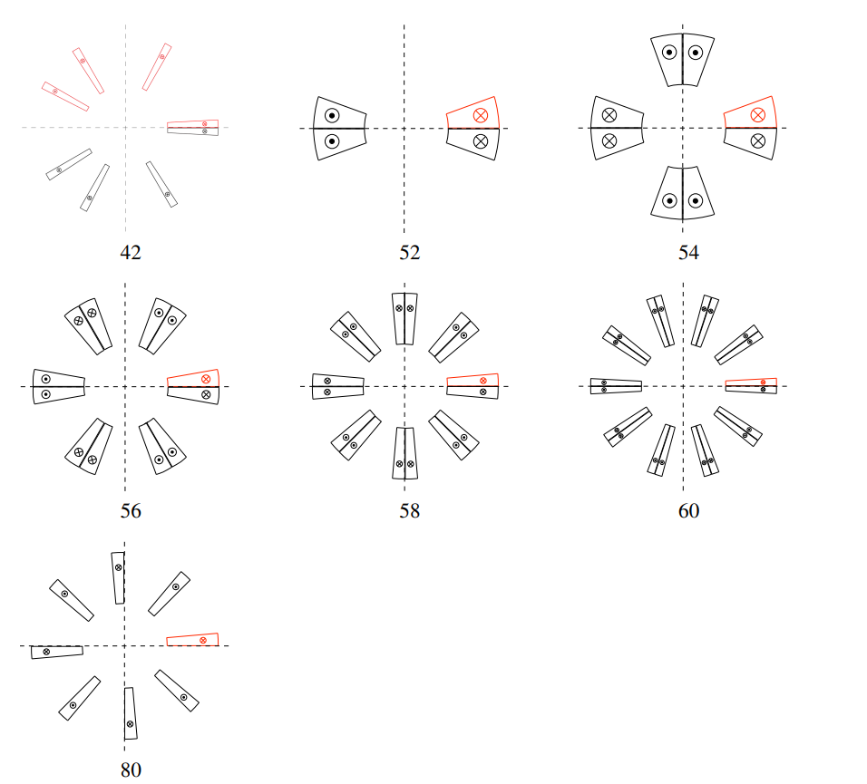
| 42 | Up-down symmetry (combined function magnet) |
| 52 | Dipole, Both Ends in 3-D |
| 54 | Quadrupole, Both Ends in 3-D |
| 56 | Sextupole, Both Ends in 3-D |
| 58 | Octupole, Both Ends in 3-D |
| 60 | Decapole, Both Ends in 3-D |
| 62 | Duodekapole, Both Ends in 3-D |
- No more than 20 blocks can be assigned to a layer per line.
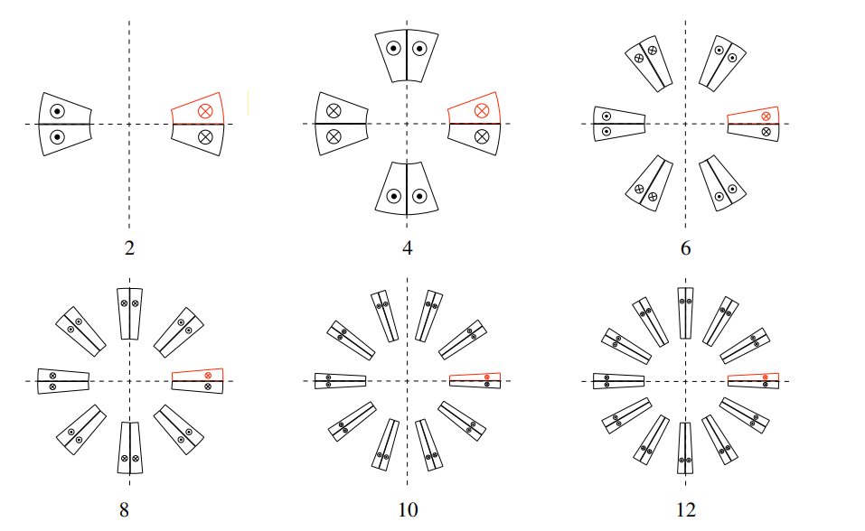
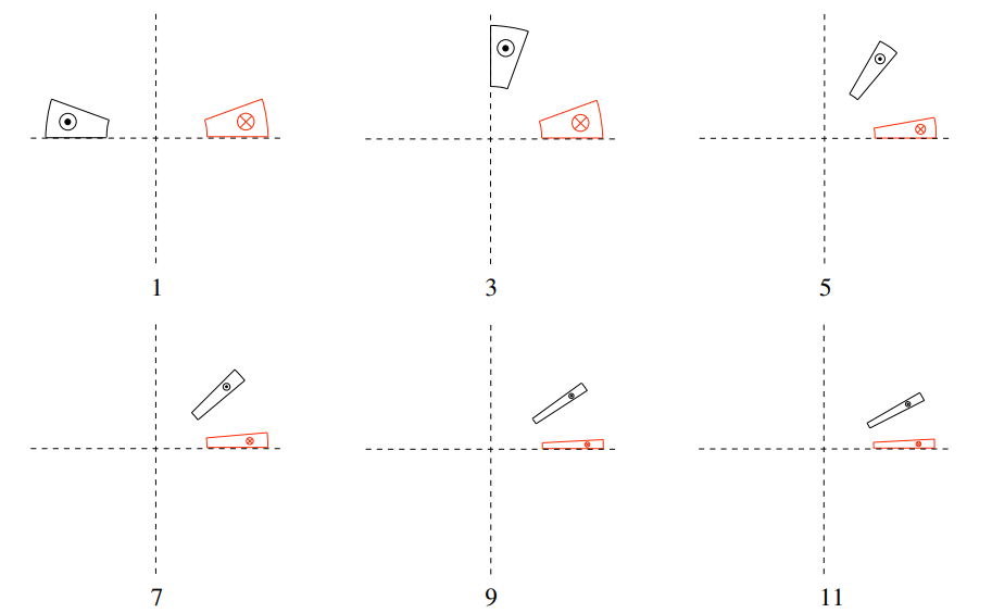
The odd numbers 1-11 define one coil only, which corresponds to one pole of the magnet. The following sketches illustrate the different options. The red block is a block entered in the "Block Data 2D"-table. The black blocks are generated by the "Layer Definition"-option.
-
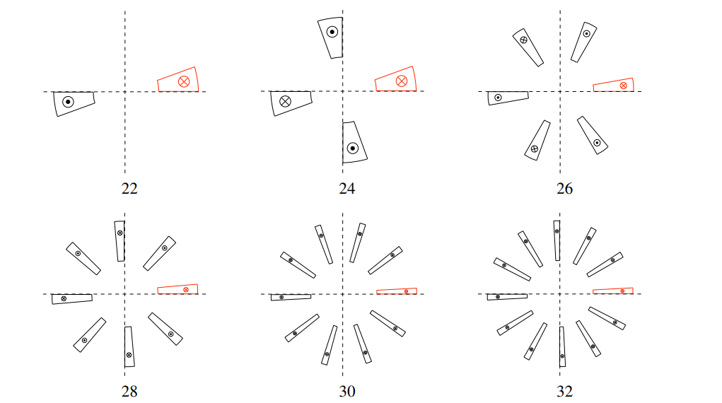
The options 22-32 are intended for return-end designs, i.e., coils with an asymmetry due to the passing of conductors from one block to another during winding.
-
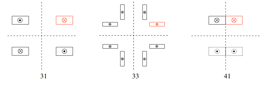
The option 31 is intended for two-in-one window frame dipoles with the apertures atop each other. The 33-option however, is designed for a single-aperture window frame quadrupole.
-
The option 41 yields the blocks in the upper half-plane for solenoid calculations, compare Section Solenoidal Magnets
-
The option 42 creates from blocks in the upper half-plane blocks in the lower half-plane with the same current direction. The option 42 is the only option which accepts that blocks be put at phi-angles larger than 90 degrees, i.e., in the second quadrant.
-
In 2-D, the options 52-60 are identical to the options 2-10. In 3-D however, 52-60 will generate an entire coil made of loops of conductors, whereas 2-12 will generate only half a coil.
Block data 2-D
Each line in the table defines one block of conductors:
| Variable | Description |
|---|---|
| No | Row number. |
| Ncon | Number of conductors in block. |
| Radius/X/Z | Radius. |
| Phi/Y/R | Positioning angle. |
| Alpha/Inc | Inclination angle. |
| Current | Conductor current. |
| CondName | Conductor Name. |
| N1 | Radial discretization of conductor. |
| N2 | Azimuthal discretization of conductor. |
| Imag | 1: Block imaged at x-axis; 0: No action. (not with "Symmetric Coil" -option) |
| Turn | Block turned by angle. (not with "Symmetric Coil" -option) |
| Ne | Number of coil-end definition that applies to this block. (only with "3-D Coil Geometry"-option) |
-
The N1- and N2-parameters are explained in Section Cosine Theta Cross Section. Setting these to values for which N1xN2 is below the number of strands given in the roxie.madata- or roxie.cadata-files yields an approximation of the actual strands by a smaller number of line currents. The total current remains unchanged. This is also a way to accelerate the calculation of time-transient effects, knowing that the accuracy of the calculation will be reduced.
-
The N1- and N2-parameters can be used to define hollow-cylinder like conductors, compare Section Cable in Conduit.
-
Note that, with regard to 3-D coil end design, a numbering scheme should be followed. Blocks are to be ordered first by descending winding radius (outer layer before inner layer) and second by ascending positioning angle.
Design variables
With the geometric modeling complete, every feature (strand, cable, block, layer) can be subjected to geometric transformations such as translation, rotation, scaling, and imaging. At the same time, constraints are defined for these operations in order to avoid penetration or physically meaningless structures. Not only can the geometric properties of the magnet be changed in the optimization process, but also its material properties such as the number of strands, current density in conductors and strands, and filling factors.
Layer:
Layer:
| Variable | Description |
|---|---|
| XSHIFL | X-Shift of entire layer. |
| YSHIFL | Y-Shift of entire layer. |
| NUMLBL | Number of conductors in block (put the original block number). |
| DRIL | Mandrel radius of block. |
| PHI0L | Position angle of block. |
| ALPH0L | Inclination angle of block. |
| TURNL | Turning layer by given angle. |
| TURNLS | Turning (but anti-clock-wise for imaged blocks). |
| RECTLA | Blocks in layer locally like "Window Frames"-option 'on'. |
| WIRELA | Blocks in layer locally like "Single Wires on Mandrel"-option 'on'. |
Coil blocks (Cross-section):
| Variable | Description |
|---|---|
| NUMCBL | Number of conductors. |
| PHI0 | Positioning angle. |
| ALPH0 | Inclination angle. |
| PHIR | Positioning angle (relative to Block n-1). |
| ALPHR | Inclination angle (relative to Block n-1). |
| PHIRS | As PHIR such that wedge is symmetric. |
| ALPHRS | Inclination angle (difference to angle giving a symmetric wedge). |
| PHIALP | Positioning angle and inclination angle equivalent. |
| GAP | Gap width of a rectangular block (relative to Block n-1). |
| PHIV | Azimuthal displacement of a block. |
| PHIVGL | Azimuthal displacement of all blocks. |
| RSHIFT | Radial displacement of a block. |
| XSHIFT | x-displacement of a block. |
| YSHIFT | y-displacement of a block. |
| ALPH0V | Increment of inclination angle. |
| RECTBL | Rectangular block. |
| WIREBL | Beam-pipe magnet block. |
| TILT | Tilt angle of rectangular block. |
| ODFAC | Conductor alignment factor (0: mandrel, 1: outer cylinder), compare the "Cond. Alignment OD"-option in the "Global Information". A number between 0 and 1 yields an alignment between somewhere between the mandrel and the outer cylinder. |
| INCL | Inclined buildup of rectangular block. |
| DFAKG | Zoom factor of cable width in all blocks. |
| DFAK | As DFAKG only in specified blocks. |
| DJFACH | Zoom factor for cable height (J=const.) in specified block. |
| DFACW | Zoom factor for cable width (J=const.) in specified block. |
Conductors:
| Variable | Description |
|---|---|
| DRI | Radius of mandrel (if "Layer Definition"-option is 'off'). |
| DHI | Height of the conductor in block specified. |
| DWO | Outer width of the conductor in block specified. |
| DWI | Inner width of the conductor in block specified. |
| DRIC | Radius of conductor. |
| DHIC | Height of conductor. |
| DWOC | Outer width of conductor. |
| DWIC | Inner width of conductor. |
| DWIOC | DWIC=DWOC=DWIOC. |
| SHIM | Cond. is a shim (current = 0). |
| XSHIFC | x-shift of conductor (xy-plane). |
| YSHIFC | y-shift of conductor (xy-plane). |
| RSHIFC | r-shift of conductor (xy-plane). |
| XSH12 | x-shift of conductor surface 1-2 (xy-plane). |
| XSH34 | x-shift of conductor surface 3-4 (xy-plane). |
| YSH12 | y-shift of conductor surface 1-2 (xy-plane). |
| YSH34 | y-shift of conductor surface 3-4 (xy-plane). |
2-D transform (Layers and Blocks):
| Variable | Description |
|---|---|
| SHIFX | x-shift of the coil block in 2-D. |
| SHIFY | y-shift of the coil block in 2-D. |
| SHIFF | Rotation (in degrees) of coil block in 2-D. |
| SHIFR | r-shift of the coil block in 2-D. |
| SHIFLX | x-shift of the layer in 2-D. |
| SHIFLY | y-shift of the layer in 2-D. |
| SHIFLF | Rotation (in degrees) of the layer in 2-D. |
| SHIFLR | r-shift of the layer in 2-D. |
Plotting:
| Variable | Description |
|---|---|
| SCALFN | Scaling factor for numbering of conductors and blocks. |
Objectives
Global values:
| Variable | Description |
|---|---|
| DCONT | Contraction factor. |
| INCLM | Mean inclination angle in magnet. |
| INCMAX | Maximum inclination angle in magnet. |
- The inclination angle measures the deviation of a conductor's radial axis from a radial positioning. The inclination angle is the sum over all conductors of the deviation from a radial position. Radial positioning is important in order to reduce mechanical stress to the cable in the magnet's coil end. The INCLM value is printed to the .output-file at every run of ROXIE.
Conductor data:
| Variable | Description |
|---|---|
| ALLIGN | Alignment constraint. |
| DTWLE | Twist per unit length. |
| R14CO | Radial position of the insulated cable (side 1-4). |
| R23CO | Radial position of the insulated cable (side 2-3). |
| F14CO | Inclination of the insulated cable (side 1-4). |
| F23CO | Inclination of the insulated cable (side 2-3). |
| DZCON | z-position of the conductor at the apex. |
Block (input) data:
| Variable | Description |
|---|---|
| PHI0 | Positioning angle. |
| ALPH0 | Inclination angle versus x-axis. |
| CURNTB | Current, all Blocks affected (for optimization). |
| DRI | Radius of the conductor in Block. |
| DHI | Height of the conductor in Block. |
| DW0 | Outer width of the conductor in Block. |
| DWI | Inner width of the conductor in Block. |
| DFAK | Zoom factor for width of conductor. |
| PHIV | Azimuthal displacement of the whole Block. |
| RSHIFT | Radial displacement of the whole Block. |
| XSHIFT | x-displacement of Blocks. |
| YSHIFT | y-displacement of Blocks. |
Block geometry:
| Variable | Description |
|---|---|
| INCLIN | Inclination angle of the last turn in bare block. |
| PHI1 | Outer angle (inner radius) of block. |
| PHI2 | Inner angle (inner radius) of block. |
| PHI3 | Inner angle (outer radius) of block. |
| PHI4 | Outer angle (outer radius) of block. |
| XPOS1 | Position in x of corner 1 of the bare block. |
| XPOS2 | Position in x of corner 2 of the bare block. |
| XPOS3 | Position in x of corner 3 of the bare block. |
| XPOS4 | Position in x of corner 4 of the bare block. |
| YPOS1 | Position in y of corner 1 of the bare block. |
| YPOS2 | Position in y of corner 2 of the bare block. |
| YPOS3 | Position in y of corner 3 of the bare block. |
| YPOS4 | Position in y of corner 4 of the bare block. |
| RPOS1 | Radius of corner 1 of the bare block. |
Plotting information 2-D
Geometry:
| Variable | Description |
|---|---|
| NUMMC | Numbering of conductors. |
| NUMMB | Numbering of blocks. |
| NOCND | No plotting of conductors. |
| WEDGE | Plot the wedges between blocks and the endspacer. Only works with the "Wedge/Endspacer"-option in the "Main Options". |
Interface options
| Option | Description |
|---|---|
| Autocad | AUTOCAD-readable file to plot the cross-section. |
| MS Excel | Comma-delimited list of corner-coordinates of each conductor. |
| Extended Printout | Extended print into .output-file. |
| 2-D Line Currents | Produces a filename.fila2-D-file which contains two tables: (1) a table with the corner points of the current-carrying areas and (2) a table with the position of the individual line currents in the model. |
| .iron File of Wedges | Only works with the "Wedge/Endspacer"-option in the "Main Options". Creates a file called wedges.iron. |
3-D coil modeling
The input parameters for the coil-end generation are the z-position of the innermost conductor of each coil-block, its inclination angle, the length of the straight section and the size of the inter-turn spacers between the conductors. For the automatic generation of the coil-end region, three options are available:
-
Coil-ends with or without inter-turn shims and conductors placed on the winding mandrel.
-
Coil-ends with grouped conductors wound on end-spacers with shelves which provide for support from below and result in an alignment of the conductors at the outer radius of the end-spacers.
-
Race-track coil-ends with or without additional straight sections. With this option it is possible to model solenoid and torus magnets.
Many options set in 2-D design have important consequences for 3-D modeling, e.g., type of coil: racetrack, cosine-theta, single wires. The 2-D options are not reiterated in this section.
Main options
| Option | Description |
|---|---|
| 3-D Coil Geometry | Tell ROXIE that we are doing coil ends. |
| Wedge/Endspacer | Only with "3-D Coil Geometry" - tell ROXIE to do endspacer design. Not available for Window Frame magnets (Racetrack coils). |
Global information 2-D
| Option | Description |
|---|---|
| Window Frames | Racetrack-type coils. |
There is an old and a new version of reacetrack coil-end generation. They are distinguished by the "Etype"-value in the "Block Data 3-D"-table. The new algorithms use end types 60 and 70, see Section 11.2.3.
Global information 3-D
The following options are available for in the "Global Information 3-D"-widget:
| Option | Description |
|---|---|
| Additional Bricks | Add arbitrarily shaped conductors. |
| Additional Leads | Add conductors that can be modeled by radius/positioning angle/inclination angle. |
| Rutherford Cable Model | This option is currently not supported. |
| Super-Elliptical Coil End | Use of a hyper-ellipse as a coil-end baseline in the sz-plane. |
| Coil Imaged at z=0-Plane | Symmetric coil w.r.t. xy-plane. The 2nd half of the coil is not plotted in postscript plots. It is, however, taken into account in field computations. ROXIE assures the correct powering of the imaged half. |
| Helical Coils | Experimental option to calculate fields and forces from helical coils (tilted solenoids, double-helix, etc.). |
- The Helical Coils option uses the "Block Data 2-D" and "Block Data 3-D" widgets for an input. The variables have a different meaning, when "Helical Coils" is switched 'on', see Section Helical Coils.
More relevant data in the "Global Information 3-D"-widget is given:
| Variable | Description |
|---|---|
| Maximum Size of Coil Ends | This number is used in the automatically produced plots (yz- and sz-plane sections of coil ends. It determines also the maximum length of endspacers. |
| Number Of Blocks in Outer Layer | The first N blocks in the "Block Data 2-D"-table are ascribed to the outer layer. |
| Cable Size Increase in Ends | The cable size increases linearly over the coil end up to the apex. The option is similar to the BULGE-option in the "Coil Ends (Differential Forms)"-menu of the "Design Variables". |
| Number of Cuts in z-Plane | Discretization density in z-direction. |
| Length of Extension into -z-Direction | Coil end starts at a negative z-value. |
-
Generally, the "Number Of Blocks in Outer Layer"-option only works with the "Symmetric Coil"-option from the "Main Options" and not with the "Layer Definition". This has repercussions on the 3-D plotting of coil ends and endspacers. The option is also commonly used to design unsymmetric endspacers for connection-side coil-ends. Here, the blocks on one side are ascribed to the 'outer layer' and two independent sets of spacers can be designed.
-
Don't use a none-zero "Length of Extension into -z-Dir." together with the "Coil maged at z=0 Plane"-option in the "Global Information 3-D"! ROXIE won't complain but the result is not reasonable.
Layers
In addition to those layer symmetry-types that were introduced in 2-D, the following geometry types are available for 3-D coil end design.
| Input | Description |
|---|---|
| 22 | Dipole Connection Side |
| 24 | Quadrupole Connection Side |
| 26 | Sextupole Connection Side |
| 28 | Octupole Connection Side |
| 30 | Dekapole Connection Side |
| 32 | Duodekapole Connection Side |
| 31 | Window Frame Dipole |
| 41 | Solenoid |
| 42 | Up-down symmetric (combined function magnet) |
| 52 | Dipole, Both Ends in 3-D |
| 54 | Quadrupole, Both Ends in 3-D |
| 56 | Sextupole, Both Ends in 3-D |
| 58 | Octupole, Both Ends in 3-D |
| 60 | Dekapole, Both Ends in 3-D |
| 62 | Duodekapole, Both Ends in 3-D |
"Connection Side" means that each block is only used to give one half of a coil end. This is necessary as connection-side coil ends are generally assymmetric. Two blocks are needed to model one arc. The "Both Ends in 3-D"-option has the same functionality as the "Coil Immaged at z=0-Plane"-option in the "Global Information 3-D"-widget.
Block data 3-D
Variable Description
Ne Row number/number of coil-end definition. Beta Beta angle. Bo Long half-axis of ellipse on cylinder. Zo Straight Section. Wi Wedge inner width. Wo Wedge outer width. Hwed Wedge height. Tend Type of coil-end (layer definition). Etype Conductor alignment in coil-end.
Design variables
Layer:
| Variable | Description |
|---|---|
| DBZ0L | Long half axis of the ellipse of coil end in block. |
| DZZ0L | Straight section of coil end in block. |
Coil Ends:
| Variable | Description |
|---|---|
| DBZ0 | Long half axis of ellipse of coil end (if "Layer Definition" is 'off'). |
| DZZ0 | Straight section of coil end (if "Layer Definition" is 'off'). |
| DZZR | Straight section relative to the previous block. |
| BETAZ | Inclination angle of block in yz-plane. |
| CENTER | Shifts the center of the turns. |
| EXTRXS | x-shift in xy-plane (saved for extrusion). |
| EXTRYS | y-shift in xy-plane (saved for extrusion). |
| EXTRPH | PHI turn in xy-plane (saved for extrusion). |
| DPERMF | Perimeter adjustment for conductor. Shift the lower edge of the conductor towards the magnet center. |
| DPERMB | Perimeter adjustment for all conductors in block. Shift the lower edge of the conductors towards the magnet center. |
| PERIMI | Perimeter adjustment for the inner surface of the specified spacer. Shift the lower edge of the inner surface towards the magnet center. |
| PERIMO | Perimeter adjustment for the outer surface of the specified spacer. Shift the lower edge of the outer surface towards the magnet center. |
| DYZS | y-shift of conductor in yz-plane. |
| DZZS | z-shift of conductor in yz-plane. |
| DYZSB | y-shift of block in yz-plane. |
| DZZSB | z-shift of block in yz-plane. |
| DYZSL | y-shift of layer in yz-plane. |
| DZZSL | z-shift of layer in yz-plane. |
Coil Ends (Differential Forms):
| Variable | Description |
|---|---|
| BOVERA | b/a-ratio. |
| HORDER | Order of ellipse. |
| BULGE | Bulge amplitude. Not to be confused with the BULGE-option in the "Objectives"-table which corresponds to the classical constant-perimeter coil end. |
| TORS1 | Additional torsion (in radians). |
| TORS2 | Additional torsion (in radians). |
| TORS3 | Additional torsion (in radians). |
| TORS4 | Additional torsion (in radians). |
-
The differential-geometry based 3-D coil-end design can now be used for field calculations and, in a limited way, for post-processing. Note that differential-geometry based coil-end design is an option for cosine-theta type magnets with the conductors aligned on the winding mandrel.
-
The BULGE-parameter lets the user simulate the bulge effect of conductors in a coil-end block due to deformations of the cable in the coil winding process. In practice, the block are often less compacted on the lower edge than on the upper edge. The bulge amplitude releases the lower outer edge of the coil-block model.
3-D Transform:
| Variable | Description |
|---|---|
| TRANSZ | z-shift of the coil-blocks in 3-D. |
| TRANSX | x-shift of the coil-blocks in 3-D. |
| TRANSY | y-shift of the coil-blocks in 3-D. |
| TRAIMZ | Imaging of 3-D coil-blocks at the xy-plane. |
| TRANSF | Turn block (in degrees) in the xy-plane to y-axis (Roll). |
| TRANST | Turn the block (in degrees) in zy-plane to y-axis (Tilt). |
| TRANSO | Turn the block (in degrees) in xz-plane to z-axis (Swing). |
| TRANIX | Additional straight section inserted in x-direction, compare Section Racetrack coil. |
| TRANLZ | z-shift of the layer in 3-D. |
| TRANLX | x-shift of the layer in 3-D. |
| TRANLY | y-shift of the layer in 3-D. |
| TRAILZ | Imaging of 3-D coil end at the xy-plane. |
| TRANLF | Turn layer (in degrees) in the xy-plane to y-axis (Roll). |
| TRANLT | Turn the layer (in degrees) in zy-plane to y-axis (Tilt). |
| TRANLO | Turn the layer (in degrees) in xz-plane to z-axis (Swing). |
- Note that when using the TRAIMZ- or TRAILZ-options, the user has to ensure the correct powering of the imaged blocks/layers. In general this means an inversion of the sign of the block current with respect to the blocks/layers that are not mirrored.
Plotting:
| Variable | Description |
|---|---|
| BLOCKC | Color index for blocks in 3-D - 1: blue, 2: dark blue, 3: red. |
| BRICKC | Color index for bricks in 3-D - 4: orange, 5: green, 0: invisible. |
Objectives
Conductor Data:
| Variable | Description |
|---|---|
| DTWLE | Twist per unit length. |
| CURVAT | Maximum curvature in the block. The geodesic curvature in a constant-perimeter coil end is calculated. Not to be confused with GEODE, the geodesic curvature parameter for differential-geometry coil ends. |
| BULGE | Bulge factor in the conductor. The bulge factor calculates the deviation from a constant perimeter coil end. Not to be confused with the BULGE-option for differential-geometry coil ends in the "Design Variables"-table. |
Block (Input) Data:
| Variable | Description |
|---|---|
| DBZ0 | Long half axis of ellipse of coil end. |
| DZZ0 | Straight section of coil end. |
| BETAZ | Inclination angle of block in yz-plane. |
Coil Ends (Differential Forms):
| Variable | Description |
|---|---|
| TORSIO | Maximum torsion in M-1. |
| NORMA | Maximum normal curvature in M-1. |
| GEODE | Maximum geodesic curvature in M-1. |
| GEOSTR | Integral of geodesic curvature squared over the entire block. Proportional to strain energy in the block in M-2. |
| EREG | Penalty if the edge of regression in the strip. |
- The differential-geometry based 3-D coil-end design can now be used for field calculations and, in a limited way, for post-processing.
Plotting information 3-D
| Variable | Description |
|---|---|
| CURVAT | Min/max curvature k on broad/narrow sides, R=1/k. This is not a curvature parameter calculated with the differential geometry method. |
| SUN | Sunshine on coil ends. |
| COIL | Plotting of coil-blocks. |
| BRICKS | Plotting of additional bricks and leads. |
| SPACER | Plotting of end spacers. |
-
Automatic generation of plots. With the "3-D Coil Geometry"-option switched 'on' in the "Main Options" a number of plots is automatically generated, whenever postscript plots are done. The first is a cut through the yz-plane. The second shows the outer layer blocks in the sz-plane in a split representation. The left half shows the lower edge of the cables, the right half shows the upper edge. The third plot gives the same split representation of all coil-blocks. Finally, the fourth automatically produced plot yields only the upper edge of all conductors in the sz-plane.
-
Also the "Wedge/Endspacer"-option in the "Main Options" leads to an automatic plot of enspacer shapes in the the yz- and sz-planes.
Interface options
| Option | Description |
|---|---|
| CNC Machine files | Endspacer Design Output. |
| Opera 8-node Bricks | 3-D bricks of the coil end for the "Opera" field calculation program. |
| Opera 20-node Bricks | 3-D bricks of the coil end for the "Opera" field calculation program. |
| Virtual Reality (3-D) | Writes a filename.wrl-file which can be opened by any VRML-browser for an interactive 3-D-view of the coils. |
| 3-D Line Currents | Produces a filename.fila3-D-file which contains information on the positioning of line currents in the 3-D coil model. |
| Input Data from 'BEND' | Read-in coil end from the 'BEND' coil-end design program. |
| Strips from Darboux Vectors | Design differential geometry-based coil ends. |
- The "Strips from Darboux Vectors"-option switches the coil-end design method from constant-perimeter coil ends to differential-geometry based coil ends.
Additional Bricks
The input for additional bricks is made in two tables. The first table describes the current in a conductor, the number of strands and the number of cuts in the conductor. The second table defines the cuts for each conductor. Choosing a conductor in the first table activates the respective second table. The table data is defined as follows:
| Variable | Description |
|---|---|
| Current | Current in the additional conductor. |
| N1 | Number of strands from corner 1 to 4 and 2 to 3. |
| N2 | Number of strands on side 1-2 and 3-4. |
| Ncut | Number of cuts to define the conductor. |
| Variable | Description |
|---|---|
| Xcut | x-coordinate of a corner of a cutting plane. |
| Ycut | y-coordinate of a corner of a cutting plane. |
| Zcut | z-coordinate of a corner of a cutting plane. |
Four lines in the second table define one cutting plane of a conductor. The number of cutting planes equals the number of bricks plus one.
Additional leads
The input-scheme for additional leads is similar to that of additional bricks. Two tables define a conductor and the positioning of the conductor in the cut planes. The first table defines one conductor type per lead:
| Variable | Description |
|---|---|
| Current | Current in the conductor. |
| N1 | Number of Strands in radial direction. |
| N2 | Number of Strands in azimuthal direction. |
| Div. | Number of divisions in z-direction. |
| Condname | Name of the conductor in roxie.madata- or roxie.cadata-file. |
| Variable | Description |
|---|---|
| Icc | Positioning of the lead: '0': the position defined by r/\varphi is in the middle between corners 1 and 2; '1': r/\varphi define corner 1. |
| Radius | Positioning radius. |
| Phi0 | Positioning angle. |
| alph0 | Inclination angle. |
| Z0 | z-position of cutting plane. |
One line in the second table defines one cutting plane of the additional lead.